


Dapeng Town Industrial Park, Tongshan District, Xuzhou City, Jiangsu Province, China
1.1 Project Overview
The roof of Linxia gymnasium adopts large span space truss structure, which has reasonable force and simple force transmission. The shortest axis of the main structure is about 92 m and the longest axis is about 156 m. The outermost edge of the main structure overhangs about 8.01 m from north to south, 21.60m from east to west, and the highest structural elevation of the roof is 22.4m. The main structure includes main truss, secondary truss, ring truss and supporting rod, as shown in Figure 1. The main truss adopts inverted triangle tube truss and the secondary truss adopts single piece tube truss. Each of the main trusses rests on two concrete columns connected by hinge supports or sliding supports. Part of the cantilever section of the secondary truss is also connected with the concrete column, and the connecting point is a sliding bearing.
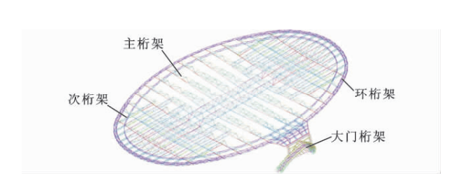
FIG. 1 Main structure truss
1.2 Construction Scheme
1.2.1 According to the characteristics of the engineering structure, the roof steel structure is divided into four zones, among which the 3-14 axis is the main truss structure zone (Zone A), and the central axis is divided into two zones A1 and A2. Outside axis 3 to 14 is the sub-truss overhanging structure area, which is divided into B1 and B2. The main components of the whole steel structure are 14 trusses, secondary trusses and 2 ring trusses. The radial main trusses are in the form of inverted triangle section, and the secondary trusses are single-piece trusses. The site installation is divided into two construction routes. Firstly, A1 area is installed, and the truss installation in this area is gradually completed from the 3-axis position clockwise. Then, the main crane is transferred to A2 area, and the truss installation in this area is gradually completed from the 16-axis position. At the same time, cantilever ring trusses should be installed first by the crane in zone B2. After the main truss in zone A1 is installed and a working surface is provided for the truss in zone B2, the cantilever regional sub-trusses should be installed clockwise, and the steel structure in zone B1 should be installed in the same order at last, as shown in Figure 2.
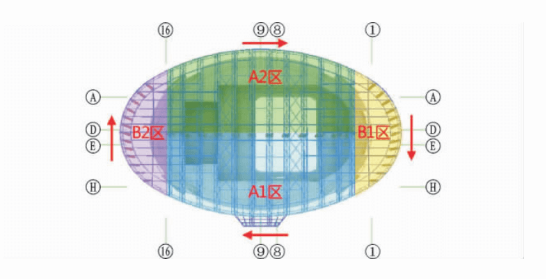
FIG. 2 Construction sequence
1.2.2 Unloading Stage
In view of the space truss structure of this project, three unloading schemes are proposed, including step-by-step unloading, step-by-step unloading and step-by-step unloading.
(1) Hierarchical unloading
Step by step unloading is to use jack step by step unloading, calculate the theoretical unloading value at the supporting tire frame in each main truss span, and determine the unloading number of stages according to the maximum unloading value (the maximum unloading of each stage is 15~20mm). FIG. 3 shows the arrangement of the tire rack. Through the return of the jack to control the deformation of the roof, to achieve a phased overall classification step by step unloading. Starting from the tire rack TJ-6 and TJ-7, the first stage of unloading is carried out symmetrically to both sides at the same time, and the second and third stage of unloading is carried out in accordance with the above order. The unloading sequence of the tire rack is:TJ-6,TJ-7→TJ-5, TJ-8→TJ4,TJ-9→TJ-3, TJ-10→TJ-2, TJ-11→TJ-1, TJ-12→TJ-23, TJ-24→TJ-15, TJ-20→TJ-14, TJ-16, TJ-19,TJ-21→TJ-13, TJ-17, TJ-18, TJ-22→TJ-25。According to the gravity load and construction load on the main structure and the displacement of the supporting point to determine the total load, and then determine the load classification.
(1) Step by step unloading at the same level
There is no classification of the stepwise unloading at the same level, and the unloading quantity at one time is the total unloading quantity. The uninstallation sequence is the same as that of storage tiers.
(2) Hierarchical synchronous uninstallation
The number of stages of synchronous unloading is determined according to the total unloading quantity of each bracket. All the brackets are unloaded at the same time for stage 1, and then stage 2 and stage 3 respectively.
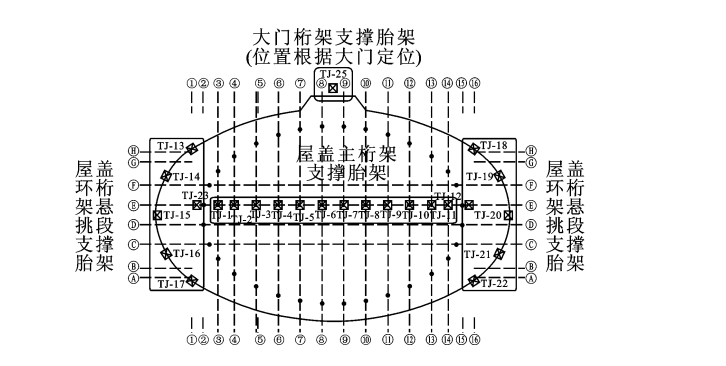 FIG. 3 Tire rack layout


