Ball joint bearing installation
One of the key points and difficulties in this project is the installation of the ball joint bearing of the space frame. There are a total of 88 spherical hinge supports, which are fixed hinge supports and rotate in two directions. If the corners are not well controlled, it will cause excessive deflection of the space frame or deformation of the rods. Therefore, the ball joint support should be installed first and temporarily fixed during installation.
The specific installation process is as follows:
- When installing the space frame, first install the ball joint support, and after the positioning review is correct, then connect the ball joint support to the embedded parts by electric welding;
- Use a temporary limit plate on the outside of the spherical hinge support to limit the position, and the limit plate is welded to the embedded part;
- The space frame support is installed on the spherical hinge support and welded according to the requirements of the drawings;
- After the installation of the space frame structure is completed, and the inspection of various indicators meets the requirements of the design and specifications, the ball joint bearing can be welded. After the ball joint bearing is welded, the temporary limit plate can be removed or left in place forever.

Steel space frame installation
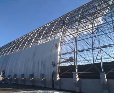
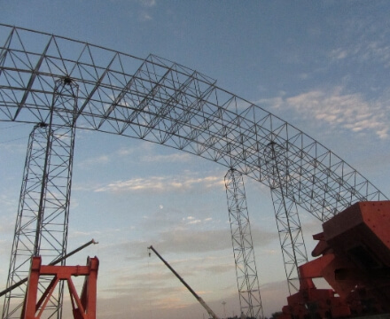
According to the characteristics of large span and tight construction period of this project, this project adopts cross-flow construction, adopts full-house high-support formwork scaffolding to set up the installation platform, and carries out the installation operation by high-altitude bulk method.
Although the amount of steel used for the space frame in this project is not large, the space frame is in the form of an elliptical shell hyperboloid structure. If the overall vertical lifting method of ground assembly is used for construction, not only a large amount of synchronous lifting equipment and technology is required, but also the force re-analysis of the space frame is required because the force of each lifting point during lifting is different from that of the original space frame. This will lead to an increase in the amount of steel used in the space frame.
In addition, since it is difficult to avoid the deformation of the space frame in the lifting and replacement, filling and other work, which has a certain impact on the quality, the method of overall lifting of the ground assembly cannot be adopted in this project.
The high-altitude assembly of high-support formwork scaffolding has a lot of advantages such as no technical difficulty, safe and reliable construction, small deformation of the space frame in place, and easily assured quality. However, the amount of scaffolding erection and dismantling is large, and it occupies the construction work surface of other types of work. Therefore, the construction schedule should be arranged in a reasonable manner to ensure that the work can be completed on time.

Deformation control of steel space frame
- The high-altitude bulk method of full-scale scaffolding shall be adopted for installation, and multiple temporary support points should be set up during the installation process to reduce installation deformation; During the installation process, the vertical deviation of the space frame should be measured at any time, and the deflection value of each node of the space frame in the self-weight order should be measured. And according to the design deflection value of the space frame, set the support point below the lower chord point of the space frame beyond the design deflection to make the space frame conform to the design deflection value of the space frame; To check the support point, it must have sufficient strength and rigidity (determined by calculation), so that the deflection of the space frame will not exceed the design value during the installation process;
- During the installation process, the measurement team should monitor at any time, adopt the node coordinate control method, regularly observe the X, Y, and Z coordinates of the spherical node, and control the maximum deflection of the node during the installation process.
Temporary support point positioning of full-scale scaffolding
a.Bracket installation method
- The scaffolding project adopts steel pipe brackets, which are assembled according to the height of the bottom of the space frame;
- Before the installation of the support, the length of the steel pipe of the support and the matching fasteners should be determined according to the bottom elevation of the space frame specified in the drawing design, combined with the base elevation of the support;
- Before the bracket is installed, the axis should be released on the ground. The bolt ball position line and the floor level control the elevation; after each step of installing the bracket, it should be leveled and straightened, and then installed upwards gradually. The bracket installation should be vertical, and the offset of every 1.5m bracket column should be ≤5mm;
- The installation of scaffolding should be neat and uniform, and there should be a support system to ensure its stability in two directions perpendicular to each other;
- When the bracket is installed, the column should adopt the docking method. The docking fasteners of adjacent vertical poles shall not be in the same step, and the staggered distance shall be ≥500mm; the distance from the docking fasteners to the main node shall be ≤h/3 (h is the step distance);
- Vertical and horizontal sweeping poles must be installed on the poles at a distance of ≤200mm from the base epithelium. When the pole foundation is not at the same height, the sweeping pole in the high place must be extended to the lower place by two spans and fixed to the pole, and the height difference should be ≤1m;
- Scissor braces and horizontal tie rods should be erected synchronously with vertical rods, vertical and horizontal horizontal rods, etc.;
- After the installation of the bracket is completed, it should be carefully checked whether the bracket is firm, and the problem should be rectified immediately;
- The scaffolding must use the nearby walls, columns and beams that have been poured as the lateral stress support points, and use vertical and horizontal horizontal rods, adjustable top brackets and wooden trusses to tighten, or hoop connection to the structural columns, to prevent overturning due to swinging left and right;
- According to the actual needs of the installation of the steel space frame, the steel scaffolding is used as the operating platform, and is built into a layered structure according to the height requirements of the lower string of the space frame, and the installation space of the space frame is reserved. Scaffolding is built in layers. The maximum erection height of the scaffolding is about 21m. The top plywood and scaffolding boards shall be fully paved layer by layer according to the installation of the steel space frame. At the dislocation of the layer height, an enclosure baffle shall be required, and scissor braces and horizontal braces shall be set in the middle of the scaffolding;
- The distance between the main bodies of the vertical poles is 1.0m × 1.0m, the step distance of the horizontal poles is 1.5m, and the width of the top surface of the scaffolding shall meet the requirements of the floor plan to meet the installation and support characteristics of the space frame. According to the specification, in order to ensure the vertical and horizontal stability of the scaffolding, scissor braces are set around the circumference and in the middle of the scaffolding, and are continuously arranged from the ground to the top surface of the operation. Row setting, spacing ≤6m, horizontal scissor braces are set every 3 steps, and sweeping rods are set at the bottom of the poles.
b.Construction precautions
The allowable deviation of the verticality and horizontality of the bracket erection should meet the requirements.
The length of the pole protruding from the top of the pole is less than or equal to 150mm. Scissor braces and horizontal tie rods should be set up in time following the installation of vertical poles. The connecting fasteners must be tightened with a torque of 40-65N·m. It is required to use a torque wrench for random distribution sampling inspection, and those that fail must be re-tightened until they are qualified. The number of sampling inspections and the quality judgment standards shall be determined in accordance with the specifications.

